5. Rotor construction
The magnet rotor is also a casting. There is also a procedure later for assembling
the parts. First collect together the magnet plates, magnet blocks, stainless wire
rope, etc. as described next.
Magnet plates
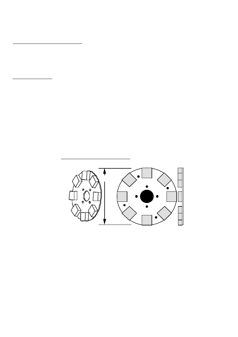
Each magnet rotor is built on a steel disk, 6mm thick. See diagram 32. Do not use
aluminium or stainless steel for this disk! The disks have to be made of magnetic
material. The disk has holes to mount it to the hub - in this manual the hub has four
holes, each 10mm diameter, on a circle at 4 inches (102mm) PCD. If a different hub
is chosen, then all the jigs and moulds must match this hub.
At the centre of the disk is a 65mm diameter hole. There should also be four holes
drilled and tapped (threaded) for M10 rod between the magnet positions, at 220mm
PCD. Screw four pieces of M10 rod, 20mm long, into these holes. These will bond to
the resin and help to secure the casting onto the disk.
32. MAGNET ROTOR DISK
305mm
The magnet plates must be flat, not warped. It is not easy to cut the outer circle
without warping the plate. A guillotine can cut steel plate into an octagon (see
diagram 33), without warping the plate. This is an alternative way to make the
rotor disk. First cut a square, draw a circle on it, and then cut off the corners at 45
degrees. The length of each edge is 116 mm.
The magnets will be placed on the corners of the octagon.
PMG manual
page 31
June 2001